Primer
A deep dive on data
center design considerations, featuring configuration and design
comments to support decisions. This essay supports the previous
Traditional Data Center Design post. This design should be taken as
a general starting point. There are plenty of modern technologies
expand on these basic principles to deliver extremely robust networks
services able to adapt to any business case. It should be noted OSPF
v2 is used in this design. OSPF v3 could be used just as easily, but
with a few design changes and configuration changes. Lastly, a data
center’s requirements are often linked to the business in which it
supports. Always design with an eye for the future.
Initial Review
Here is an overview
of the topology to be reviewed

After completing
this much of the data center, the GNS3 VM running the environment is
pegged at 100% CPU utilization. Perhaps more cores are in order.
Device Overview
- The routers DLC01
and DLC02 represent the network CORE. This is the heart of OSPF area
0. Any inter pod communication should flow through these devices. In
reality, these should be extremely fast line rate layer 3 switches
with 10, 40 or 100 Gbps interfaces.
- Inside of our
“Protected Infrastructure” pod, DL-P-INF-D01 and DL-P-INF-D02
represent the distribution \ aggregation switches. These should be
layer 3 switches as well, but scaled to the planed pod requirements.
They also provide layer 3 connectivity for servers\applications
through different VRFs. PRO-INF-ZBFW represent a firewall
appliance(s) to separate the VRFs into different security zones.
- DL-P-DEV-D01 is
another device simulating another pod. The configuration here is done
enough to inject different prefixes into the routing domain.
Networks
Not only will it
make life easier, OSPF almost requires a hierarchical IP network
design. Therefor, it is best to think of everything built in blocks.
Each component is a smaller part of the larger. The data center site
is the largest block, with different IP networks assigned.
In this case, the
production 10.75.0.0/16 supernet is assigned to the entire data
center. Every pod will then take a smaller block of these addresses
to provide network access to all services inside of that pod. If this
method is followed, every production server will ultimately be
assigned an IP address out of this block.
There is also a
transit supernet, 10.175.0.0/16, assigned to the data center. Using
this method keeps network addressing independent of production
servers. Again, each pod is assigned a smaller block of addresses for
layer 3 transit links. It is also a good idea to get into this
thought habit to make transitioning to IPv6 a little easier.
Generally, fewer IP addresses are required so a smaller transit block
can be carved out for each pod.
Management networks
are up for debate. can vary based on requirements and available
management suites. If possible, it is a good idea for management
traffic to not route over production links, unless there is a failure
on the management infrastructure. This provides a true out of band
scenario, ensuring that production failures do not hamper the ability
to manage any part of the network. Management devices could have
their own data center pod for this backup, but should have unique
hardware paths in and out of the data center.
Following this
hierarchy allows for efficient IP summarization at every level. Other
data centers only need to know a particular supernet to reach any
device inside another data center. Inter data center network
advertizements would be nothing more than a handful of supernet
prefixes. To go further, each data center core would have a couple
prefixes advertized from each pod. Outside of a special case, each
pod would only need to have a default route up to the core. This
becomes very important to devices, such as firewalls, not explicitly
built to contain very large route tables.
Examining the Network
Core and General OSPF
The CORE of the data
center is fairly flat; meaning that there are no VLANs and special
VRFs
(other than for
management), only transit links running a single OSPF process. It’s best
to keep redistribution and other routing tricks off of these devices.
QoS is okay, otherwise complexity should be kept to a minimum.
Where possible,
transit links are built on physical interfaces (not SVIs) with /31
networks to conserve address space. Since these links are effectively
point to point links (a direct connection between two devices), OSPF
interfaces can be configured as point-to-point.
First, we’ll look at the configuration between
DLC01 and DLC02; then, the
reason to use point-to-point vs the default broadcast OSPF
interfaces.
| CORE 01 | CORE 02 |
|---|---|
DLC01#show run | sec router ospf router ospf 175 auto-cost reference-bandwidth 10000 area 0 authentication message-digest passive-interface default no passive-interface GigabitEthernet1/0 no passive-interface GigabitEthernet2/0 no passive-interface GigabitEthernet3/0 network 10.175.0.0 0.0.0.255 area 0 DLC01#show run interface GigabitEthernet1/0 ! interface GigabitEthernet1/0 description Intra-CORE Transit Link ip address 10.175.0.0 255.255.255.254 ip ospf message-digest-key 1 md5 ospf-75-area0 ip ospf network point-to-point negotiation auto end DLC01#show ip ospf 175 neighbor Neighbor ID Pri State Dead Time Address Interface 10.175.0.254 0 FULL/ - 00:00:32 10.175.0.1 GigabitEthernet1/0 10.175.0.253 0 FULL/ - 00:00:34 10.175.0.11 GigabitEthernet2/0 10.175.0.251 1 FULL/DR 00:00:32 10.175.0.21 GigabitEthernet3/0 |
DLC02#show run | sec router router ospf 175 auto-cost reference-bandwidth 10000 area 0 authentication message-digest passive-interface default no passive-interface GigabitEthernet1/0 no passive-interface GigabitEthernet2/0 no passive-interface GigabitEthernet3/0 network 10.175.0.0 0.0.0.255 area 0 DLC02#show run interface GigabitEthernet1/0 ! interface GigabitEthernet1/0 description Intra-CORE Transit Link ip address 10.175.0.1 255.255.255.254 ip ospf message-digest-key 1 md5 ospf-75-area0 ip ospf network point-to-point negotiation auto end DLC02#show ip ospf 175 neighbor Neighbor ID Pri State Dead Time Address Interface 10.175.0.255 0 FULL/ - 00:00:35 10.175.0.0 GigabitEthernet1/0 10.175.0.252 0 FULL/ - 00:00:34 10.175.0.13 GigabitEthernet2/0 10.175.0.251 1 FULL/DR 00:00:38 10.175.0.23 GigabitEthernet3/0 |
This area of the network only contains traffic
traversing one area of the network to another. As such, the supernet
wild card mask is used to add all the transit links to the OSPF
process. This will allow for minimal needed configuration to add new
areas to the network; however, the “passive-interface”
configuration should be made default to allow for a more managed
control of how these new areas are brought online. Another method
would be to enable OSPF on an interface only when ready to form a
neighborship, either through the network command or interface area command. It could be argued that if it is desired to enable OSPF on a per interface basis, using OSPF area interface configuration would be cleaner than multiple network statements. If network statements are used, the specific IP address with a 0.0.0.0 wildcard mask would be the easiest to interpret and reduce the chance of error.
OSPF, as a complete protocol, will be covered
in more depth in later posts. This, though, is a good time to point
out a few beneficial OSPF configurations in the data center. Again,
these points are only a start to optimizing OSPF for a particular
environment.
-
Point to Point links – By default, Ethernet interfaces run as “broadcast” OSPF network types. This is due to the broadcast nature of Ethernet, allowing for the DR-BDR process. If there are only two devices in an IP network, as in a point-to-point transit link, there is no need for a designated router or the DR election process. Configuring transit interfaces as point-to-point OSPF networks will speed up the convergence time after recovering from a failure. There is a caveat that the hello-interval for non-broadcast networks increases from 10 to 30 seconds, the dead-interval (4 times the hello) increases from 40 to 120 seconds. It could be argued that failures on point to point transit links in a data center would be more physical in nature and would not rely on the hello-interval for failure detection.
-
Fast Hello – Enable OSPF fast hellos for sub-second failure detection (maybe there is concern of software failure) on broadcast or point to point links. Fast hellos are configured on an interface basis. Due to CPU issues, this is not a feature enabled in this example.
-
Auto-Cost – Data centers have faster, more stable interconnects. It is a good idea to scale OSPF metric algorithms to account for these faster links. By default, OSPF uses a reference bandwidth of 100 Mbps over Ethernet links, meaning everything from 100 Mbps to 100 Gbps+ will be evaluated as an equal cost. If a Data Center has transit links of 40 Gbps, it may be a good idea to set this as the cost algorithm’s reference bandwidth. The reference bandwidth configuration is process specific and should match across the entire OSPF implementation. When setting cost or the reference bandwidth, remember the maximum OSPF metric value of 65535 that represents infinity. This shouldn’t be an issue with a well designed, hierarchical implementation.
Pod Connectivity – Distribution \ Aggregation
Distribution\Aggregation
section of each Pod is where the OSPF ABRs live and the real magic
happens. This is where Pods interface with the rest of the network.
Traffic egress
to the CORE has been
subjected to firewall packet inspection. Traffic ingress
from the CORE will need to be routed to the appropriate VRF, through
the associated firewall.
Traffic summarization between the CORE and access portion of the
network also occurs here. The distribution layer is a unique VRF
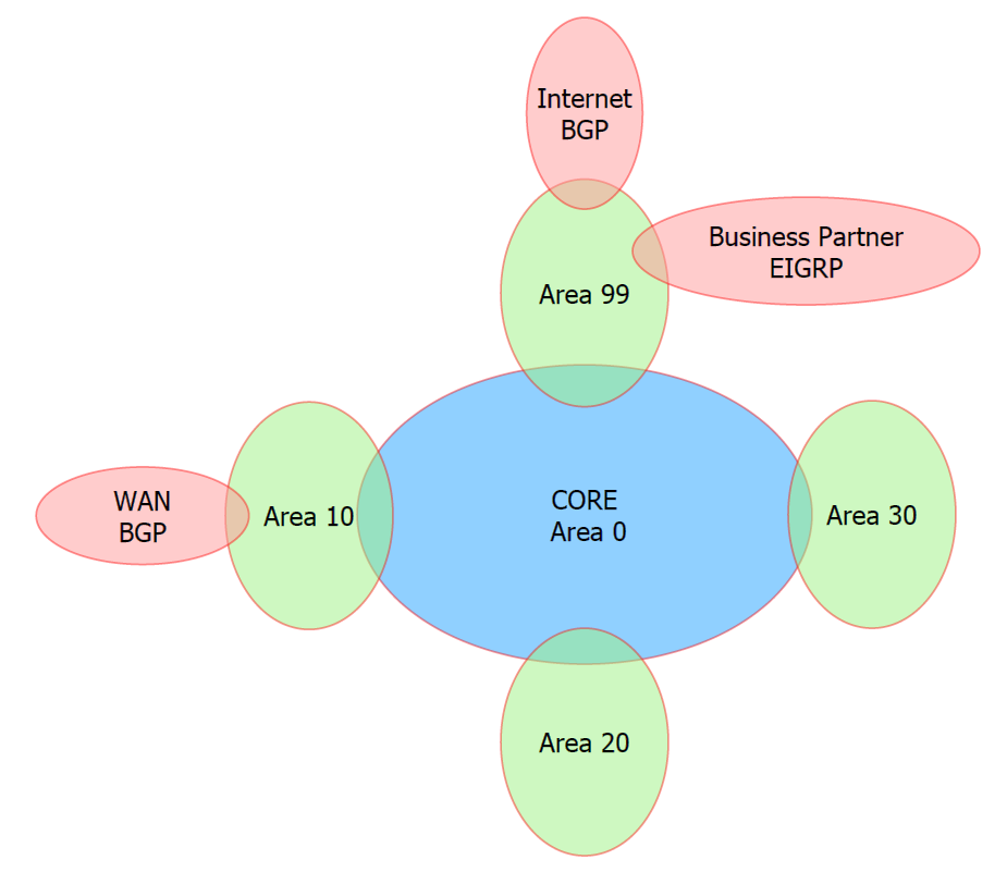
connecting OSPF area 0 of the CORE to the access OSPF areas\VRFs.
Outside of special circumstances, the distribution layer should be
the only section of the network with multiple OSPF areas. (Note:
in this example topology, the distribution VRFs are named CORE to
show that they interface with the data center CORE.)
Below
is a mock up of a simple Pod. It attempts to detail two switches
chassis of “Pod 01”. In each switch chassis, we see three VRFs:
CORE, APP_TRUST, and APP_UNTRUST. It is important to notice that
intra-Pod VRFs cannot communicate without routing through a security
device. The application in this example is assigned OSPF area 10 and
exists across two VRFs. There is no set number of application VRFs or
OSPF areas assigned to a Pod;
however, logic and switch
capabilities should be taken into account before growing a Pod too
large. Lastly, if more that one OSPF area is used, remember that
inter-area communication is required
to route through OSPF area 0. Lastly,
ADC services are shown for reference, but are outside the scope of
this document.

Pod OSPF Configuration
Here we look at the OSPF configuration of all the OSPF processes that exist in a Pod. Since each VRF is a virtual route table, each VRF will require a separate routing process. Since a similar IP hierarchy is used in each Pod, referring to the network diagram at the top of this document will help to understand the configuration, especially summary statements.
| Distribution 01 | Distribution 02 |
|---|---|
DL-P-INF-D01#show vrf Name Default RD Protocols Interfaces CORE |
DL-P-INF-D02#show vrf Name Default RD Protocols Interfaces CORE |